Monday, 16 December 2013

Cooling

Why cooling is important


Electronic chips generate noise and heat during use: your digital camera or smart phone gets progressively hotter the more you use it. Sensitive applications, such as astrophotography MUST eliminate this heat, as heat is noise, black sky will be grainy black sky.
This heat is also present with the RTL stick, appears as frequency drift and internal noise - radio will not stay on a frequency.
Gain applied in Configuration panel increases heat, hunt weak signals and need to increase gain = increases internal noise generated by the stick.
Improve cooling - reduce noise.
Recently introduced temperature-controlled oscillator promises to solve this issue, around 50 dollars. Regular RTL stick sells for 8 USD. Hmm.

Do you need to worry about it?

No: Leave the stick warm up for 15 minutes - half an hour, let it reach thermal equilibrium, after stick is warmed up set ppm correction. My particular stick drifts 4 ppm from cold to warmed up, then stays on frequency.
Yes: You are a perfectionist, or you want less internal noise with high gain settings.
Performance increase with modifications below will be really, really small, less noise on shortwave, maybe one or two less noisy lines on WXSat images.

Air cooling

The brain of the stick lives under the plastic cover, open up the stick and drill holes, especially above the black squares, or leave the board bare without its plastic cover.
Stick will run cooler, frequency drift will be reduced somewhat.
Heat-sinks are a possible solution, reliable connection is hard to achieve due to small surface area, edge of the chip can break off.
Additional airlow with PC fans, run on 5V, telephone chargers can be used. Two PC fans installed outside a PC power supply case, with stick in the middle provides a cheap air-cooled solution.

Using fans have the following drawbacks: 1) Needs external power source, 2) magnets in close proximity to the stick, 3) the awful sssssssh noise fans generate.

Water cooling

Electricity plus water equals disaster, insulator (hot glue or epoxy) must be used to seal electrical components from water. Tried several methods back in the Pentium 4 days, messy, expensive, hot glue won't dry evenly, epoxy eats components: water cooling is unsuitable.

Oil cooling

Place stick into metal can, with antenna and USB cable connected and led through lid of can, position stick middle of can, slightly above bottom.
Pour sunflower or vegetable oil into can with the RTL stick inside, completely fill up can.
Repeat: fill up can as much as you can, any interior surface will pick up condensation.
Cover with lid, plug in USB and connect antenna, fire up SDRSharp.
Oil will provide cooling, it is not conductive, see stick blue light on image below.
RTL-SDR, Software Defined Radio

Place can in the fridge or freezer: sunflower oil theoretically has a very low freezing point, practically after one night at -20 degrees Celsius can will be very cold to touch.
Active heating is unnecessary, oil volume and metal can surface will be enough to dissipate heat.

Cherry on the cake: FM Noise Reduction

Metal can also acts as a Faraday cage, FM broadcast pickup will be greatly reduced.

Traditionalists love to place stick in metal enclosure for the same reason, not realizing that heat buildup will effect performance - a chip running at a very low temperature will have lower internal noise and greater performance.

Cleaning stick after oil cleaning

Stick should not be connected to computer or any other electricity.
Lukewarm water in sink, spoonful washing powder or cup of liquid detergent, the more the better, dissolve until glassy reflection and feel of glove on hand. Pour liquid detergent on stick/  place stick and USB cable in washing powder, wash off oil and detergent with lots of water.
Repeat steps above 2-3 times, wash hands, clean with towel / toilet paper.
Leave stick to dry for a day. small heat, not close to radiator, never on top of a heater.
Will be good as new.

If you enjoyed this article, or wish to support this blog, 


... go to Amazon and buy my book Tips and tricks in the book will save time and money, reduce frustration with computer settings and help you build the best antenna system from shortwave to microwave. Detailed and illustrated step-by-step descriptions on easy-to-do antennas, from shortwave to microwave.
Basically all you need to know to enjoy radio.

Friday, 4 October 2013

Beginner Antennas

Moved to rtlsdr4everyone.blogspot.com, redirecting in 5 seconds We have moved, redirecting in 5 seconds This is an auto redirect page.

Sunday, 29 September 2013

Ham-It-Up vs SDR Up 100

RTL-SDR, shortwave, comparison, shootout, review, Ham-It-Up, SDR Up 100, adapter, SDRSharpThe Ham-It-Up and the Up 100 are the two cheapest shortwave adapters available: direct competitors at 50 USD (including shipping).
For this review, I purchased the Ham-It-Up and received the Up-100 for free for testing.

Shipping and customer service


The Ham-It-Up comes from the States with tracked shipping; you get emails where it is, but when the package leaves the US no more tracking info available. You can buy on Ebay, Amazon or via the manufacturer's website.
The Up-100 ships from Croatia (that's a country in Europe next to Italy) with no tracking. You pay when the item arrives, so no shipping worries. Available by sending an email to Adam: adam9a4qvwashington@yahoo.com, remove the US capital to get his proper email.
Nooelec: Local postal service lost my first order, so after some Ebay hassle they sent a replacement one free of charge. Nooelec also included 3 adapters for free, to compensate for the inconvenience.
Adam: Upconverter arrived quickly, seller replies almost immediately, will help you with antennas, cables and power options. I requested a power lead to power the SDR-100 and received one free of charge.

Ham-It-Up First Impressions


Your 50 dollars from Nooelec arrives in an anti-static bag, protected by two bubble-wrap envelopes. The Ham-It-Up fits in your palm, looks and feels impressive; first thoughts were "This will get the job done, money well spent and just look at that beauty".
RTL-SDR, shortwave, comparison, shootout, review, Ham-It-Up, SDR Up 100, adapter, SDRSharp
Brain Game: SDR-Up 100 on left, Ham-It-Up on right
You get a piece of electronic component separately, the brain of the thing, which you have to push in; there are no written instructions in the envelope, a YouTube video shows assembly.
A chunky switch enables pass through mode, so if you use an outdoor (preferably discone) antenna you can use the same antenna for shortwave with a flick of a switch.
In comparison, the Up-100 works out of the box, no fitting or manual assembly required.
I want equipment that works when I get it: Adam's upconverter is better here.
Both upconverters add 125 MHz to the received frequency, so the only major difference is power options, usability and, ultimately, performance.

Power and size


The Ham-It-Up needs power between 4-6 Volts: the square USB-B cable used for printers and some external hard drives powers it.
Works with any of the following options:
1. Directly from laptop, USB port supplies power. Distance from computer limited by USB cable length.
2. Mains USB adapter, then USB cable powering the upconverter. Plug-in USB chargers work  fine for this purpose.
3. 12V from a car battery or similar supply, 12V to 5V adapter which is widely available (called 12V to USB adapter).
4. Four rechargeable or normal batteries supplying between 4.8 V and 6V, then power via USB-B cable.

Unless you power the Ham-It-Up from your laptop, a USB-B cable must be cut apart for power.
Connect the USB-B square bit into the Ham It UP, Red and Black to battery terminals and you're in business: green light comes on when it has power. This is better than the Up-100 which has no light to show it works.
The Up-100 will fit into an electrical junction box, the Ham-It-Up needs a bigger enclosure.
For marine use, without testing for performance, choose the Up-100, no power adapter nor special cable needed, smaller enclosure and works with boat or car-standard 12V.

Testing setup
RTL-SDR, shortwave, comparison, shootout, review, Ham-It-Up, SDR Up 100, adapter, SDRSharp


You need as much wire outdoors as possible for the frequency you're interested in; the lower the frequency the more wire you need.
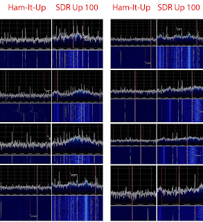
If you have a discone antenna you're better off with a short wire than your discone, see results on your right. Higher peaks = better signal, more fun.
City centre location, 20 foot wire as antenna for testing, coax with ferrites to upconverters.
Laptop with 8GB Ram, Core i3 Processor running Windows 7 64-bit if you want to know.
During setup same antenna, RTL-SDR dongle, Gain at 0dB, same SDRSharp settings used throughout.
The two upconverters were set up side-by-side, only swapped antenna and signal cables.
Tested both day and night, sunshine and rain, strong and weak signals.
Offset: I do NOT use offset in SDRSharp, simply enter 125 MHz plus the desired frequency. Tune to 125 MHz, you'll see a huge spike, your real tuned frequency starts from there. 129 MHz becomes 129-125 = 4 MHz and so on. SDRSharp crashes or fails to start for me with - 125 offset, plus some mental arithmetics won't hurt.

Performance
RTL-SDR, shortwave, comparison, shootout, review, Ham-It-Up, SDR Up 100, adapter, SDRSharp

Update 2: More pictures with different gain settings at the bottom of the post

Update 4: Due to Nooelec's response I feel compelled to insert their observation here (full reply at the end of article)


There is no chance that the 'Ham It Up' could possibly perform as well as it should without any gain in front of it. It's not a fair performance comparison. If anything, you should certainly specify as much in the performance section of the article.

Conclusion: the Up-100 is better. Much better.
Ham-It-Up: trying to understand speech, fading.
Up-100: the room is full of voice, more noise too, but Digital Noise Reduction takes care of that.
Weak signals are simply not there with the Ham-It-Up. I can hear them with the Up-100.
The difference is so huge that when changing upconverters I stopped double-checking which one is in use, as the Up-100 is so much louder.
The Ham-It-Up gave me the impression of a dusty, old shortwave handheld, which tunes the major stations with lots of noise and fading; and you're happy with it, 'cause at least you hear something.
With the SDR-100 the feel is more of a sensitive, cutting edge equipment, able to receive faraway stations.

Room for Improvement


- More power options. Thick Red and Black wires for 9-15 V power when I need them, standard USB extension cord connectors when I want Plug and Hear.
- LED for power. SDR-Up 100 needs an indicator to show all is fine; both need flashing LED to remind me to change batteries when the battery starts to die.
- Simple enclosure for an extra 5 euros.
- Two antenna sockets for HF and VHF work, big switch between the two. I don't want to change antennas.


Final thoughts
RTL-SDR, shortwave, comparison, shootout, review, Ham-It-Up, SDR Up 100, adapter, SDRSharp

At least, you can receive shortwave. 
The Ham-It-Up is an excellent product for listening to major broadcast stations with an outdoor discone; the pass-through switch enables simple and quick exploration of signals below 30 MHz without the need to change antennas. Powered with an USB cable, the package takes up little space and is easy to use: if you see a signal in SDRSharp chances are you'll hear something. 
Apart from that novel fact there's no reason to buy one.
Compared to the SDR-100, the Ham-It-Up is so deaf it needs a hearing aid. To put this into perspective, the Ham-It-Up with a 6m wire is about equal to an ICOM IC-R5 (small communications receiver) with an outdoor discone, and comparatively worse than a Grundig G3 with a built-in telescopic antenna. Simply put, the SDR-100 is light years ahead for weak signals, at the cost of noise pickup. At half the size a suitable enclosure is easier to find, and 9 and 12V power options are just the cherry on the cake.
If you are new to shortwave radio spend your 50 dollars on a second-hand portable from eBay.
For everyone else, I recommend the SDR-100 over the Ham-It-Up.

Update 1: Shielding, Aerials, Settings and Images


Due to an interesting comment on RTL-SDR.com let me clear a few things... Regarding this post and in general my attitude to testing, usability and, ESPECIALLY, cost.

50 USD results in an upconverter from either manufacturers, so you can listen to shortwave signals. Both lets you do that, but due to the built-in amplifier the SDR-UP 100 lets you receive more signals.

Neither up-converters were placed in an metal box, so level field here. RTL stick in a metal box plus all the tricks I detailed in the noise suppression post.

The aerial question: the maximum I can or will put out is 20 foot wire. The results show a dramatic difference between the two.
Obviously, you can improve reception with more wire, as 20 foot wire is far from ideal. Or an UNUN. Or an antenna tuner. Or moving to the countryside, try 40m wire in an urban environment from a third-floor flat.

I am interested in utility and value for money out of the box, so a beginner can read understandable information on which one to choose to hear faraway radio stations - and the SDR Up 100 is better for this purpose.

The number-crunching game is pointless for beginners: the primary target audience for this blog are yachties without AIS moaning that a receiver is expensive, people on a budget, non radio people exploring the world of RTL-SDR.

Leave comments here please

Comments are much appreciated, especially if you leave them on this blog, so I can reply them here. Unfortunately, you have to have an account for that, with a name, maybe even a face like some of us do.

Update 2: Comparisons with different gain settings


Tested both upconverters on 5053, 5910, 6134, 7350 and 9419 kHz, with four and five different gain settings. Click on the frequency numbers to download printscreens below, one file is around 13-14 Mb. 
I consistently found the SDR UP 100 better. An example is 5053 kHz: extremely faint Portuguese voice with the SDR Up with lots of noise, short-wave info tells me possibly R Jornal a Critica FM on 5055kHz. Still, playing with Noise reduction and Gain at the same time results in understandable speech. With the Ham It Up, no matter how I tried I could not get the same results, since I have to increase gain in SDRSharp up to a point where noise swamps the signal. 


Update 3: Reply from Adam, the maker of SDR UP 100.


Adam has to say about my suggestions:

"Regarding your notes for the improvement, they are all in place.
The guide line when constructing the upconverter is to have the unit with costs up to 50 USD.
I have plenty addons and improvements that can be included in the design but then, it will not cost the 50 USD but 100 USD and then we are entering another price level.

I agree, with a small investment, the various power connector system can be added.
The cost of the led diode is minor and all gadgets are not so expensive.

My first idea was to have a descent reception using the peace of wire, because this is the unit built for those users who will use a peace of wire, and the unit shoul be able to receive the signals with that antenna.
If the unit require full size resonant antenna, than this is not the product for everyday user.

If you compare this upconverter together with the stick against the expensive 800USD sdr receivers the difference is only that they have the dedicated bandpass filters, attenuator and a better AD converter."

Many thanks for the above. Adam can be reached at adam9a4qvwashington@yahoo.com, remove the US capital to get his proper email.

Update 4: Reply from Nooelec, the maker of the Ham-It-Up.


Your review is thorough and well-written. I find it great that you covered aspects other than performance.

However, the performance review is not even close to apples to apples. As you are aware, there is no LNA on the 'Ham It Up' upconverter itself. There are quite a few reasons for that. 

1. An LNA on-board limits options as it would be fixed-gain. Variable-gain would be exceedingly expensive.
2. An LNA should really be placed near the antenna if the antenna run is long. That cannot be done if it is built into the upconverter.
3. The appropriate gain should be dependent on the frequency or frequencies of interest and antenna being used.

There is no chance that the 'Ham It Up' could possibly perform as well as it should without any gain in front of it. It's not a fair performance comparison. If anything, you should certainly specify as much in the performance section of the article. 

If you really wanted to do a better comparison, you would either insert the same amount of gain in front of the Ham It Up, or take the signal from after the LNA on the Up-100 and insert into the Ham It Up upconversion path. If you need assistance with this please contact us. 

You also fail to note that there are advantages to a socketed oscillator, as on the Ham It Up, insomuch as it can be very easily replaced with an even better clock-source for those who have one at their disposal. We ship the oscillators off-board so that it is more likely to survive international transit.

The Up-100 is a good upconverter, much better than other designs we've seen. We have one here at the lab that we have used to compare performance. The performance is very similar with the same amount of gain in front. This is not surprising, since the actual frequency mixing is done by the same ADE-1 and the Up-100 uses quality filtering components as does the Ham It Up. The only differences you should see when doing a legitimate comparison test is the differences between the filtering components used on the two upconverters.


Update 5: Thoughts after manufacturer's responses


Deep respect to both manufacturers for replying to this review; it shows that both truly care about their product. I added Nooelec's response to the performance section as suggested as it was a good idea.
The reason I did this review is to find out which upconverter is better for 50 USD; I define better as more enjoyable, easier to use, capable of providing a signal I can listen to, out of the box.
Some readers fail to grasp the fact that both upconverters cost 50 dollars, so they are competitors. LNA or no LNA. A friend asks me which one to buy: I point to the SDR Up 100. Ham It up for 30? Sure. Same price? SDR Up 100.
Out of the box, you hear more with the SDR UP 100. Even after playing with gain settings, I could not get the same performance out of the Ham It Up.
At the end of the day you pay your money and you take your chances: order both, enjoy both.

Ham-It-Up technical information and user Guide here: https://code.google.com/p/opendous/wiki/Upconverter#SDR_Software_Tuning_Instructions

If you enjoyed this article, or wish to support this blog, 


... go to Amazon and buy my book Tips and tricks in the book will save time and money, reduce frustration with computer settings and help you build the best antenna system from shortwave to microwave. Detailed and illustrated step-by-step descriptions on easy-to-do antennas, from shortwave to microwave.
Basically all you need to know to enjoy radio.

Friday, 13 September 2013

Review: SDR UP 100

What you need to know: for 50 USD you get the same performance as a dedicated shortwave receiver, easier to use with better sound quality. Recommended.
RTL-SDR, shortwave, Upconverter

HF Upconverter SDR Up 100


Available from the following website: http://upconverterup-100.blogspot.com.
Works by adding 125 MHz to the signal received, so your RTL stick will understand signals below 30 Mhz. It also has a filter, so signals above 55 MHz will not bother your reception.
Costs 40 euros / 50 USD delivered to your door, delivery to Ireland took 5 days. You pay for the item via PayPal when it arrives, so no worries for shipping.
It is physically small, about the size of a Zippo lighter. Antenna IN and antenna OUT connectors are SMA female.
Amplification is built-in, automatically increases the received signal 63 times (18dB). It is so effective gain in SDRSharp must be set very precisely, even one move on the control panel will kill all received signals (called overload).
Power is supplied via two pins, in the bubble wrap envelope an A4 page shows schematics, so you can identify positive and negative. Soldering and antenna connectors are first-rate, looks and feels solid. In over six weeks of testing and after connecting antennas many times there is no play, no movement.
Works with 9 to 15 volts, so a brick 9V battery or a 12 V car battery works. Manufacturer says 50mA draw, real-life mobile performance is 7-8 hours from an unbranded 9V battery. There is no visual indicator, no LED to show if power is OK, battery dies = stops working.
At home I power it with a dedicated car 12V battery. No top-up charge for the last six weeks - still works OK.

Testing Setup


6 meter (20 foot) wire from a window, connected to coax cable - Upconverter - RTL stick. City center location, electrically very noisy.
Noise reduction as per the precious entry on this blog, ferrites on the coax going to the antenna wire.
Automatic Gain control turned off in SDRSharp, set in Configuration between 2-5.
Set the frequency at 125 MHz plus the frequency of interest, so 132 MHz displayed will be 7 MHz.
Sampling rate at 1.024 MSPS so I see 1 MHz chunk of the radio spectrum. Broadcasting signals are continuous, easily identifiable from the waterfall display.
Digital Noise Reduction is your friend with strong stations: click on a peak or line in the waterfall display, set pleasurable noise limit, get astonishing voice quality.

Performance
RTL-SDR, shortwave, Upconverter


No number crunching here; I go by my ears. All the usual players come in easily, propaganda from Radio China International, Voice of Russia / America / Korea etc are like FM broadcast. You do not have to turn a dial or remember a setting - save the frequency, set noise reduction and enjoy.
Tired of speech? Ethnic music from the Middle East, religious programming from the States, man hitting stuff with kitchen utensils from the Far East all booming in. I have the adapter for over six weeks, still every night I sit down with expectation and a "what tonight" attitude - the ease and accessibility, combined with easy station saving rekindled my interest in shortwave.
Filtering works, the strongest local FM station barely audible when tuned.
Looking for distant signals? With only a 6 meter wire I got understandable speech from the Caribbean, Caribbean Beacon from Anguilla on 6090 kHz.
Fun for a long time; Morse code and digital mode transmissions are a possibility, if you're into fiddling with software. For HF Fax I recommend JVComm32, thought the local fishermen and NOAA satellites at 137 MHz are more colorful.

Standalone vs software defined - price, usability, fun


Standalone: 80-100 USD for a good one, 200 is top-of-the-range, 5000+ USD for pro equipment. With bargain basement 20 USD wonders you buy frustration.
RTL stick advantages: huge screen to see signals, easier tuning, better speech quality.
Standalone radio advantages: compact and portable solution, works off cheap batteries, no learning curve. Turning dials instead of clicking a mouse, more intimate "what-comes-next" feel.
Buy a shortwave adapter if you're happy with computer-based solutions or you need to use capabilities for a goal, e.g. Weather charts or decoding digital modes.
Order a good shortwave receiver such as the Eton G3 for 100 USD if you need standalone capability, a backup or wish to listen to far-flung signals without a laptop or the hassle of mating radio and a laptop.
The best is both: get this upconverter for home, especially if you have suitable space for antennas, and enjoy your portable while out and about. For nature outings (I hate city electrical noise) I always have a laptop with the discone and the QFH taking up the back seat, so the upconverter and wire is not a factor. For a shorter period the portable soothes the withdrawal and good enough with the telescopic antenna. 

Competition


Direct competition is Nooelec's Ham-It-Up upconverter for the same price, thought the Nooelec one has a pass-through switch so you only have to connect a different antenna (or use an antenna switch) for frequencies above 30 MHz. Watch this space, I have one on order for a direct comparison.
Around 70 USD you'll get upconverters with two or three antenna inputs.
100 USD and up RTL stick and shortwave adaptor integrated into a USB stick, but I think at this point the primary advantage of software defined radio (Price) disappears.
200 USD buys a stick (Funcube Dongle Pro) for all signals this side of microwave, better performance then an RTL stick (at 15x cost)and no hassle with drivers.

Final thoughts


For half the price of a good shortwave receiver the same performance on your laptop - you give up buttons and tactile feel, and gain ease of use and accessibility.
The number of broadcasting stations, amateur operators and digital modes on shortwave is staggering; for the 50 USD admission fee you get an easy-to use adapter with good performance. On expensive and dedicated shortwave receivers the frequency display screen and the buttons are small; with this setup I can see 1 MHz worth of signals in Full HD on a 24" screen.

Further reading and useful websites


Shortwave background info if you're new to the topic (Wiki): http://en.wikipedia.org/wiki/Shortwave_radio

Available HF upconverters glossary here: http://blog.kf7lze.net/2012/09/14/round-up-of-rtlsdr-upconverter-choices/

To know what you're hearing see Short-Wave Info.

English shortwave broadcasts are listed on Primetime Shortwave.

Shortwave antenna info at http://www.w8ji.com/long_wire_antenna.htm

Wednesday, 4 September 2013

Reducing electrical noise

RTL-SDR, EMI, RFI, Noise reduction, noise suppression, SDRSharp,

- You can use alu foil, but make sure it touches the metal part of the USB plug.
- Remove the metal support from the USB extension cable on the end where you connect the RTL stick. This will eliminate noise picked up by the USB extension cable.
 - If you have a spare car battery, connect the metal part of USB plug to the negative terminal.
- Mobile operation or no car battery? Wrap the center conductor of coax around the metal part of the USB plug, then place the stick in the middle of coiled coax.

Testing setup

Your antenna receives noise and signal. Without an antenna any signal received is by the RTL stick and the cables, and you do not want that.
For this test: Nooelec RTL-SDR 820T stick, max gain, no antenna. Weak local FM radio station signal 5/5, clear and enjoyable. That is unwanted signal entering the reception chain.
On the images the middle signal is the radio station - that should not be there, smaller peak is better.
Also note the waterfall display for received signal strength.

RTL-SDR, EMI, RFI, Noise reduction, noise suppression, SDRSharp, Results


Direct vs USB cable connection: USB cable (76cm) increased noise by 13 dB.
USB plug metal connected to 1m coax: coax cable center conductor connected to the metal support of the USB plug. Decreased noise by 7db.
USB plug metal connected to 10m wire: further noise reduction by 5dB.
USB plug metal connected to 12V car battery negative (-) terminal: noise almost completely eliminated.
USB plug support connected to 10m coax, RTL stick nesting in the middle: noise completely eliminated.
Aluminum foil, metal cans, metal enclosures: aluminum foil NOT touching either the antenna jack or USB connector, half roll of aluminum foil: no effect. Metal from Seven 0.5 l cans wrapped on top of the alu foil: no effect. Metal enclosure: no effect. Note that if the alu foil/metal/enclosure is connected to the metal part of the USB plug, immediate noise reduction of 15-20 dB, station still heard, speech distinguishable.

USB connector mod
RTL-SDR, EMI, RFI, Noise reduction, noise suppression, SDRSharp,

A reduction of 10 dB, stick still safely connected.
Remove the USB metal part that keeps the RTL stick in place,  from the end of the USB extension lead where you connect the RTL stick. 
Only USB signal and power connectors remain. Mow  shielding in the cable is not connected to the signal chain.
Do not remove the other end of the USB extension lead, the one going into the computer USB port, no further reduction realized, but the extension cable will easily come out of the port.

Organize cables at home


If it has a plug or battery, it will radiate electrical noise, either the cable / power lead or the actual device itself.
A simple solution is to place cables and extension leads into a computer case or a similar metal enclosure.
In the following example, unmodified original RTL stick, no antenna so it only picks up noise, connected with 1.24m (5 foot) USB extension cable. Stick resting on the edge of the PC case where I keep cables/extension leads.
PC case panel off: Local station washed away in electrical noise, audibly louder noise.
PC case panel on: Relief from the loud noise, local station understandable.
If I'm after a distant signal: laptop unplugged, electricity turned off in the house, candles on. Optionally: LNA and shortwave upconverter running off batteries.
Best is no electricity: listen to a far-flung Caribbean station in candlelight with your significant other.

Ferrites


Ferrites are rings, beads or clip-on pieces of iron used to reduce noise.
Coil the USB cable around a ferrite ring, or use clamp-on ferrites.
Use ferrites at the terminations of your
- USB cable between computer and stick,
-  on the cable between stick and antenna.

6-7 dB reduction of noise visible, audible decrease of the FM station with 4 turns on a ferrite ring and ferrite beads on the USB cable (USB plug metal removed both ends).
Also did experiments with turns around ferrite rings - 8 turns made no difference.
Conclusion: invest in clamp-on ferrites, the bigger and more, the better.

Maximum noise reduction

Stick wrapped in alu foil, foil touching the metal part of the USB plug, connected by an USB extension cable with the metal removed. Stick inside a metal enclosure, in the middle of 10m coax coil.
Result: no signal whatsoever, FM band is clear, waterfall is uniform blue.
Optional: ferrites if you have them.

Closing thoughts

If you chase very weak signals, such as shortwave with an upconverter, or a weather satellite just on your horizon you need the best noise reduction solution.
In all of the above tests I had gain to the maximum, so any reduction is clearly visible.
Noise as called here (same thing, complicated words):  electromagnetic interference (EMI) or radio frequency interference (RFI).
You know a better option? Curious to hear from you, use the comment section here.


Note on Nooelec: As their customer support might recommend the hardware guide on this blog, Nooelec sent a free RTL-SDR stick to my former high school physics lab.
I like this attitude.

Friday, 30 August 2013

Review: LNA4ALL Antenna Amplifier

Summary: buy one, works as advertised.


What is it?

LNA, RTL-SDR, SDRSharp, ADSB, Weather Satellites, AIS, antenna, setup, testing, review, comparison, DIY, Homebrew,

A small electronic device making radio signals 100-150 times stronger.
Officially called a low-noise amplifier, LNA for short.
Costs 25 euros delivered,
helps you hear and see more targets of interest.

Why?


- To run the RTLstick with less gain,
- To get the maximum from your antennas,
- To add range to your reception ability.

Testing setup

Commercial radio, airplane speech, Weather satellite signals, AIS and airplane position signals are tested. If the LNA delivers as promised on these frequencies, we can assume that it will also perform in the band of your interest.
Antenna is a broadband, commercially-available discone to eliminate antenna errors.
No number-crunching for the review, check the images for exact dB values.
I paid for my LNA, and have no business connection with the manufacturer.

Commercial radio / Upconverter range
LNA, RTL-SDR, SDRSharp, ADSB, Weather Satellites, AIS, antenna, setup, testing, review, comparison, DIY, Homebrew,

Signal strength increase as promised.
This band if of particular interest to those who have an upconverter for shortwave reception.

LNA, RTL-SDR, SDRSharp, ADSB, Weather Satellites, AIS, antenna, setup, testing, review, comparison, DIY, Homebrew, Airband


Performance slightly better than expected.
Airplane chatter between Plane and Approach/Tower/Ground comes booming in, much better audio, pilot seems talking to you.
Also tested with an Icom IC-R5 handheld receiver, no need to use outside discone as clear reception indoors.

LNA, RTL-SDR, SDRSharp, ADSB, Weather Satellites, AIS, antenna, setup, testing, review, comparison, DIY, Homebrew, NOAA, APTWeather Satellites / NOAA APT reception


Signals are visibly stronger in the waterfall display (quickly connected the LNA during a recent pass), less banded noise in images, same noise floor requires less gain in SDRSharp.
As less gain is required, the stick runs cooler, less internal noise is generated, images are clearer.  

Marine Band / AIS
LNA, RTL-SDR, SDRSharp, ADSB, Weather Satellites, AIS, antenna, setup, testing, review, comparison, DIY, Homebrew, AIS

Increased gain step-by-step until all four vessels in port showed up in Shipplotter, first by MMSI, then by name.
Amplifier connected only half the gain was necessary, performance on par with manufacturer specification.


Airplane position signals / ADSB
LNA, RTL-SDR, SDRSharp, ADSB, Weather Satellites, AIS, antenna, setup, testing, review, comparison, DIY, Homebrew, NOAA, APT

Without ampifier, maximum range is 46nm (83km).
With the LNA, maximum range is 52nm (94km).
ADSB Sharp with Tuner AGC on, adsbScope for monitoring, maximum range and aircraft not dropped selected. Monitoring local traffic for few hours and using range rings to establish maximum range, all equipment including antenna height (4 metres or 12 foot) the same during testing.


Ordering and customer service 


The LNA under review is available from this website: LNA For All.
Contact the seller, Adam directly via email for orders: adam9a4qvwashington@yahoo.com/ Remove the capital of the USA to get his real email: name (4letters) and callsign (5 characters).
Seller only charges you when the item arrives, no worries over items getting lost. Payment via Paypal.
Shipping to Ireland took 5 working days, amplifier in a bubble wrap envelope with drawings.
Communication is good, questions via email answered quickly, technical shortcomings revealed openly.
Amplifier worked out of the box.

What you get


A small circuit board, no power supply, no instructions where goes what, no clue how it works except for a diagram showing components and performance.
If you know radio, soldering and electronics, it will make sense, if not, you will turn your 25 euros around, wondering what to do with it and where to start.
The manufacturer states that a "Turn a key solution is delivered" - that's not true. You have to provide power to it.
Note to manufacturers: Please send boards - or make it an option - with a red and black wire for power connector. This nonsense with USB connectors, pins and holes should stop. 

How to make it work

LNA, RTL-SDR, SDRSharp, ADSB, Weather Satellites, AIS, antenna, setup, testing, review, comparison, DIY, Homebrew, NOAA, APT(This is my solution, LNA operational in 10 minutes. Solder if you can or want to)
In the envelope you get a drawing, bottom left of the page shows a picture of what you have, with writing such as GND and + 8-15VDC.
Get a small screw, screw it into the third hole from the left BY HAND.
Too much power = too big screw.
Screw goes through = small screw.
Easy does it, should be just a little bit of resistance as you turn.
That screw is electrical power, plus on your battery.
All the holes in the four corners are negative, minus sign. Use screws, this time falling through the hole, to create four legs, similar to an oil rig.
Create support so the screws to hold the board in place - use a non-conducting material. Ideas: cigarette filter tips (works), scrap plastic from coax cables (might need multiple layers), wall plug fixings (currently in use).
Connect a wire to the screw sticking out from the positive, third hole from top left, by wrapping the wire around it. Write plus sign on it so you know later.
Connect a wire to one of the screws in the corner, this will be negative.

The above method is in use for the last three weeks, the four legs are perfect support for mounting inside a junction box or on a piece of wood.


Power and mobile operation 

Works with 9 to 15 volts.
Officially no over-voltage or wrong polarity protection. My experience is:
It seems indestructible: if the preamp receives 9V to 15V, connected properly, it will operate.
Seems to survive user errors:
- 12V car battery, connected the wrong way: amplifier survives.
- 12V car battery, short-circuited during operation, sparks everywhere: survives.
- Amplifier mounted on top of antenna, no enclosure nor protection, heavy rain: works.
- Rain on amplifier: all works fine.
A great advantage is that either inexpensive 9V batteries can be used for mobile operation, or directly powered by 12V car batteries; no converter needed.
Mount it inside an electrical junction box, power it with a 9V battery and you're ready to go.

If you enjoyed this article, or wish to support this blog, 


... go to Amazon and buy my book Tips and tricks in the book will save time and money, reduce frustration with computer settings and help you build the best antenna system from shortwave to microwave. Detailed and illustrated step-by-step descriptions on easy-to-do antennas, from shortwave to microwave.
Basically all you need to know to enjoy radio.

Friday, 23 August 2013

Weather Satellites - Software

For about 25 euros you can receive a weather satellite image like this one.
RTL-SDR, SDRSharp, WXtoImg, QFH, Software Defined radio, weather satellite image

What is this all about?

Around 800 km / 500 miles above your head, weather satellites circle Earth, continuously sending back what they see. You can receive this signal with an RTL stick and create a similar image to the one on the right.
Setting up software is just as important as a good antenna, so this guide details software settings.
Please read Weather Satellites - Antennas for a suitable antenna and construction tips.

Why?


- Real-time observation of weather systems in your area
- Confirmation of other data received, such as WEFAX or NAVTEX signals
- Promotes understanding meteorological phenomenon such as lows and highs in colour
- Receiving an image from a satellite 800 km above your head is fun, educational (Doppler shift, atmospheric propagation...) and lets you view Earth in glorious detail.

What you need

To create an image you need an antenna to receive the signal, software to understand this signal (SDRSharp, free), and imaging software to create an image from this signal (WXtoImg, free).
I assume you have an RTL-SDR stick and installed the software to use it. If not, read the Software Guide on this blog.
The imaging software, WXtoImg can be downloaded from here:

http://www.wxtoimg.com/downloads/wxinst21011.exe

Installation is easy, and once the work flow is understood works very well.


Weather Satellites Background information 
RTL-SDR, SDRSharp, WXtoImg, QFH, Software Defined radio, weather satellite image
Polar Orbit - Image from NOAA

(no need to read this to get an image, but good to know)

Officially called NOAA 15, 18 and 19, they are truck-sized digital cameras with a radio link to Earth. Imagine your digital camera circling an orange, always over the top and bottom of the orange, the North and South Pole. The orange, Earth, is also spinning, so the camera always sees a different part.
Satellites continuously take a picture of the earth beneath them, sending this signal back to earth in a way similar to TV signals in the 80's.
Because satellites constantly move, you can only see them at a given time.
It's a very simplified explanation, read References at the bottom for more info.

Computer tips and setup


I use a mid-range laptop with Core i3 processor, 8 GB RAM, running Windows 7 64-bit.
Also tested laptops with 1 and 2 GB RAM, was unable to receive images.
Weaker computers can not process the signal and decode said signal at the same time.

Get better images by
- disabling any screen savers (Right click on Desktop, Personalize, bottom right corner)
- disabling programs running in the background - small arrow pointing up next to Speaker icon at the bottom right of your screen shows you what you're running.
- disconnecting wireless mouse and keyboard
- NOT fiddling the touchpad or playing with settings in SDRSharp.
Wireless routers had no influence on received images.
The RTL stick is covered in 5 layers of cut up aluminum cans, connected to the laptop with a 1 metre extension cable.
Antennas are connected with 5 metres of 75-Ohm cable. Tested reception with 17 metres of cable, no difference in received images.
Connectors are BNC, or cables twisted together. Makes no visible difference.
For antennas read the Weather Satellite Antennas section.


SDRSharp Settings


This software uses the signal from the antenna and sends it to the imaging software. You need the following settings:
RTL-SDR, SDRSharp, WXtoImg, QFH, Software Defined radio, weather satellite image

Mode: WFM. Others will NOT work.
Bandwidth: Write 40000 here, 50000 maximum.
Squelch: Off
Audio Slider: set it to about 70 percent.
Input: Cable Output
Output: Cable Input
Frequency: You can enter it directly or use the buttons on the top of the screen. Only three frequencies are used - you get them from the imaging software.
Satellites are only visible for your radio from a given time, so run SDRSharp 5-10 minutes before the satellite appears. Always double check WFM, 40000, and the Audio settings.
Sample Rate: Selecting 1,024 MSPS in Configuration works better.

Gain settings


(Explaining how to get the best signal-to-noise ratio. Skip if you're familiar with this)

Setting up gain in Configuration is the difference between good and bad images.
Open up Configure (right to Play and left of the numbers) and see the slider - this controls gain of the stick. More gain (slider to the right) - more signal and noise.
Noise is electrical signal you're not interested in - the waves at the bottom of the screen are noise.
Signal is what you want - usually a peak in the top display and coloured dots in the bottom screen.
Now move the slider slowly to the right and watch the waves (noise) at the bottom rise. Just about when they start to rise is a good starting point.
Find a local signal - if you have a big airport nearby google "Airport Name" ATIS - this should give you the airports' info broadcast frequency, tune to it with the big numbers. Hear a voice repeating Landing Runway 30? Good. No airport? Find a local radio, the signal must be continuous.
RTL-SDR, SDRSharp, WXtoImg, QFH, Software Defined radio, weather satellite image

Note the height difference between the signal (the mountain) and the noise (the waves). Increase gain (move the slider to the right) and find the point where the height of the mountain in relation to the waves are the biggest. Stop there.
Congratulations, you've set up SDRSharp for the maximum signal-to-noise for that frequency.
For weather satellites use this as a starting point, check the image (description on how to below) and increase/decrease according to the image.
Increasing gain to maximum will also increase noise, decreasing the height difference between the mountain and the waves. You do not want that.

WXtoIMG settings


Get the latest satellite information: go to File, then to Update Keplers. This gives you the times of satellites. With WiFi it was automatic for me, if not working, go to Options - Internet Options. Information what the software is doing: Bottom left of screen (above blue Microsoft circle) shows you what's happening.
RTL-SDR, SDRSharp, WXtoImg, QFH, Software Defined radio, weather satellite image
Satellite Pass List, important is the time and frequency of the satellite. The program gets the Time Zone and Date from Windows Settings.
Selecting a good satellite pass: the MEL in Satellite Pass list shows the maximum height of the satellite for your location. Zero is the horizon, 90 is directly above you - higher the number, more signal, better image.
Location setup: Under Options - Ground Station Location enter your location. Latitude: North is plus, South is Minus. Longitude: East is Plus, West is Minus. Unsure of your location? Google the name of your town with coordinates added after the name of town, e.g. Dallas Coordinates gets you 32.7758° N, 96.7967° W. That will be Lat  32.7758, Long - 96.7967 (West  = minus)
Audio setup: Under Options - Recording Options Select Cable Output, so the imaging software can hear what the radio software is saying.

You're ready to go.

Checklist before receiving your first satellite


Do the startup checks 15 minutes before each satellite. During the satellite pass no Facebook, no movies, or you will get horizontal bands in the picture.
Connect your stick to the laptop. Run SDRSharp with no antenna attached, test local radio stations - if you can hear them, you need to block the signals by adding more layers of metal around the stick.
Connect your antenna, check again local radio stations. You should see peaks, indicating that the antenna is properly connected.
Start WXtoImg, check the next satellite pass time and frequency.
Tune to the given freqency in SDRsharp. Mode WFM, Bandwidth 40000, No Squelch, Audio to almost maximum, Cable output In and Out selected.
Press play in SDRSharp.
Switch to WXtoImg, File (top left), Record (seventh from top), bottom of the screen press Manual test.
Check signal level. Bottom right of the screen, small meter with number in the middle should be green colour, number should be between 50-60.
If yellow, audio is not loud enough - Increase in SDRSharp.
If red, audio is too loud - Decrease in SDRSharp.
All good? Go to File, then press Stop - second from the bottom.
Check complete, peace of mind that software is working properly.

Receiving the image
RTL-SDR, SDRSharp, WXtoImg, QFH, Software Defined radio, weather satellite image


SDRSharp should be running, check again for WFM, 40000, Audio level and CABLE settings.
Start imaging software, go to File, then record. Second option is Record and Auto Process, Check the square next to Create images.
Press Auto record. WXtoImg waits for a satellite, bottom left of screen tells you the name, time, and frequency.
As soon as the satellite appears on the horizon the bottom of the screen changes, program starts recording and you'll start to see something.
RTL-SDR, SDRSharp, WXtoImg, QFH, Software Defined radio, weather satellite imageFirst you'll see only black and white dots, then black and white rows, adding up to something hopefully resembling a satellite image.
Let the software finish, then check your final image.
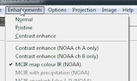
Final image is always black and white, you can add color with Enhancements - MCIR Map Colour IR.

Problems

Black image only - signal from radio software is not reaching imaging software. Squelch is turned on, or proper CABLE settings are not selected.

White and black dots - something is in the way of the antenna so it can not hear the signal.
- Place the antenna higher up, or move somewhere with a clear view of the horizon.
- If you can not see the picture at all maybe 1) the antenna is not ok 2) not WFM selected 3) wrong frequency.

Small bands or rows in the image
RTL-SDR, SDRSharp, WXtoImg, QFH, Software Defined radio, weather satellite image

- Antenna hears an other transmitter. Move to an electrically quiet place like a forest park, nature reserve or a field.
- Your computer generates noise. Use ferrite beads on the USB cable for the stick or coil the cable in a small circle.

Image is too white or too dark (usually too dark)
The gain in SDRSharp is too much - decrease it slightly. The small bands at the edge of the screen is a good place to start, ideally you should see different shades of gray.

Image is shifted, lines on the sides not vertical
In WXtoImg, go to Options (fourth from left), then press Resync (sixth from top). One or two lines out of sync might remain, you can't help that.


Tips and tricks


- Print off the satellite pass list in PDF format and keep it on your desktop. Install PDF printer software (doPDF recomended, download from here, opens in new window),then you won't need to open WXtoImg to check the times of the next pass. Saves time for a quick check.
- Check, then double-check settings in both SDRSharp and WXtoImg, because the two programs must work together for best results.
- WFM gives you the best picture.
- 40000 as it is a nice big number and only requires two buttons. I've seen no difference with 45000. It can not be less than 37000.

Noise-free images are a result of:
A good antenna - build a QFH (read Weather Satellite Antennas to find out how)
Clear view of the sky - no trees, buildings between you and the antenna
No electrical noise - cover the stick in metal, move out of the city.
Satellite high on your horizon - choose a satellite from the Satellite Pass list with a MEL as close to 90 as possible. MEL Numbers less than 30 are usually full of banding and noise. Image on top of the page is from a pass with an MEL of 87.
Pre-amplifier - also called a low-noise amplifier, it increases the signal more than a hundred times. The gain in SDRSharp is only needs to go up to 28 db, so less internal noise is generated in the stick. A good one costs 25 euros, currently testing one.

References and Further Reading

Satellite info

NOAA 19 on Wikipedia.
National Oceanic and Atmospheric Administration NOAA 19 Spacecraft Status Summary
A technical description of how the satellite sends the signal to Earth by NOAA.
Satview - lets you track where is your satellite in real time. Combine with SDRSharp to show you signal strength, WXtoImg for the transmitted image, then resize program windows so they fit on the same screen and watch in real time. Image will be probably ruined, but still, great entertainment.

RTL-SDR, SDRSharp, WXtoImg, Turnstile, Software Defined radio, weather satellite image


Some historical background, an interesting read, people were already chasing satellites with large handheld antennas in the 70's.

WXtoImg

WXtoImg Installation and Quick Start Guide

Similar guide

RTL-SDR NOAA Guide: http://www.rtl-sdr.com/rtl-sdr-tutorial-receiving-noaa-weather-satellite-images/

If you enjoyed this article, or wish to support this blog, 


... go to Amazon and buy my book Tips and tricks in the book will save time and money, reduce frustration with computer settings and help you build the best antenna system from shortwave to microwave. Detailed and illustrated step-by-step descriptions on easy-to-do antennas, from shortwave to microwave.
Basically all you need to know to enjoy radio.


Weather Satellites - Antennas

Summary: two meters of wire and a meter of coax for a good antenna, 5 meters of wire and
RTL-SDR, SDRSharp, WXtoImg, QFH, Software Defined radio, weather satellite image
a wood frame for an excellent antenna.
Cost is less than 10 euros, construction time is maximum one hour for the example here.
Read on to find out how.


Your antenna choices for Weather Satellites are:


1. Monopole with 4 radials. Construction detailed in the AIS antenna guide, elements are 54.5 cm long. Not discussed here.
2. Turnstile. Four wires plus two coax cables. Portable version discussed here, takes 30 min to build.
2a. Eggbeater - add more wire to the turnstile. Tested, better signal strength. Option if don't want to build a QFH.
3. Double Cross / Lindenblad: Complicated to build, not suitable for marine use.
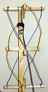
4. QFH, short for quadrifilar helix. A support with four arms, holding 5 metres of wire. Weather satellites use this type - build this.
5. Yagi-Uda: the TV antenna type found on chimneys, requires manual tracking. Not discussed.

Materials


Wire - the thicker the better. Center conductor from cables work, better results with house grounding wire. I use 3mm (No 6-10 AWG for metric readers) solid copper wire with insulation left on. Some guides use 1/4" or 8mm copper tubing, needs special tools.
Support - your choice. I use wood as it's easy to work with, cheap and readily available.
Connectors - screw terminal blocks are great to hold wires in place.
NOTE: WEAR EYE PROTECTION!
Grounding wire comes as two or three 3mm cables combined in one cable. When uncoiled for measuring / cutting, it can hit you with sufficient force to take your eye out. Pieces being cut also fly to surprising distances.

I've built and tested different versions of the following antennas, best performance with easiest construction is discussed here. Form follows function, so the results might not be aesthetically pleasing, but they work.

Portable Turnstile


Built and tested six different versions, received the image on the right with the version below.
Officially called a crossed dipole, basically four horizontal wires with a phasing harness (more on that later).
Wire lengths are either 1.09m (half-wave) or 54.5 cm (quarter wave). Longer length gave no visible improvement and a pain to mount / carry around.
Wire diameter can be either center of coax cable (1mm) or grounding wire (3mm). Theoretically thicker is better, this is true, thicker cable gave better signal strength.
Phasing harness is coax cable cut to a specific length. Some guides recommend 50 and 75 Ohm cables, tested multiple versions, could not see any difference in received image. If googling turnstile antenna for images, you might notice that sometimes only one cable is used on top of the assembly.
I found that having two 75 Ohm cables, four terminal blocks, 3 mm grounding wire and a wood support is a quick, easy and portable solution.
Wires are removable with a screwdriver, making for a compact and transportable package.
RTL-SDR, SDRSharp, WXtoImg, Turnstile, Software Defined radio, weather satellite image


Materials


Wire - Cut four (4) 55 cm wire. Remove the insulation for 5mm on only one end.
Cable - You need two cables of a specific length. The length required depends on the insulation type around the center conductor. Strip away the braid and check the material surrounding the center wire.
If it is plastic, you need 36 and 72 cm long cables.
RTL-SDR, SDRSharp, WXtoImg, Turnstile, Software Defined radio, weather satellite imageIf it is foam (same material as a coffee cup, soft to the touch) you need 43 and 86 cm long cables.
Leave space on each end of the cable so you'll have enough cable to work with. Separate braid and center wire. Folding the center wire onto itself makes for a better connection at the block.
Screws - self-tapping screws (they make their own hole as you turn them) are great.
Wood / mounting block - mount the components on a piece of wood, or inside an enclosure.
Terminal blocks - one end holds the wire, other end connects the cable. Screw one of the screws fully in. This will be a stop for the radials, e.g. the 54.5 cm wire. Also test that the wire fits into the terminal end tightly.

Assembly
RTL-SDR, SDRSharp, WXtoImg, Turnstile, Software Defined radio, weather satellite image


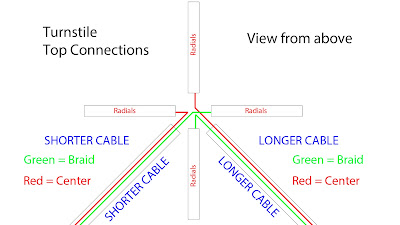
Mount the four terminals at 90 degrees to each other, like North, East, South and West on the compass rose. Leave enough space in the middle for the cables.
Opposing ends of the four terminals are connected, so they form a North-South and East-West pair for each of the coax cables. Push the center of the braid into the hole of the screw connector, and tighten the screw. I find it easier to do the braid first, then the center.
Connect the shorter cable: center to West, braid to East. Insulate braid and center as the other cable might come into contact with it.
Connect the longer cable: center to North, braid to South. By leaving enough center and braid to work with assembly is much easier.
Connect the other end of the shorter and longer cable with the cable going to the RTL stick - connect the three center to center and braid to braid. Insulate braid and center separately.
Locate the four 54.5 cm wires, and one by one push into the terminals, fixing them down with the screw.

Congratulations, now you have a turnstile antenna!


Transform this to an eggbeater antenna:


The eggbeater antenna is an improvement on the turnstile, using two loops, each around 220 cm long, so they form a  71 cm diameter circle. The commercial version is used by radio amateurs to communicate via satellite. If you have enough wire give it a go.
Connect the ends of the 220 cm loops into the terminal connections. That's it, the phasing harness you made will be fine, same principle.
I found that even thought the signal is better, it is too large and does not look nearly as cool as the spiral QFH.
Besides, why not build the antenna type actually used on the satellite itself?


RTL-SDR, SDRSharp, WXtoImg, Turnstile, Software Defined radio, weather satellite imageQFH, the Spiral antenna


Built eight versions, easiest to construct with best image quality described here.
The image on the right was made with chopsticks taped to a brush to form the frame, with coax cable for antenna elements. Length and distances are critical, materials are not. 
The antenna is made from a smaller and longer piece of wire, fixed to a frame, connected at the top. Google the term QFH - and a huge number of websites, guides and images come up. Recommended ones are included at the end. However, most guides require the use of power and heating tools and/or soldering.This guide shows you how to build a working version quickly with basic hand tools.

Materials

Frame support: Your choice. I recommend wood, with self-tapping screws only a screwdriver required.
Coax cable: due to the wide variety of cable around, their different properties and the pain of connection on the top and bottom NOT recommended.
1mm wire: the required circular shape is easily lost, signal strength is barely adeguate.
3mm grounding wire: RECOMMENDED, keeps its shape quite well.
Copper rods: you need heating and soldering equipment, pipe cutters etc. Theoretically the thicker the better, comes down to tools and personal choice.
Build one with smaller wire first, then progress to thicker materials.
Connectors, screws: as for the turnstile.

Dimensions


Use the calculator here: John Coppen's Online calculator.
For 3mm grounding wire, use bending Radius: 5mm, Conductor Diameter: 3mm.
Press Calculate - do not press Enter, you'll get an error message.

RTL-SDR, SDRSharp, WXtoImg, Turnstile, Software Defined radio, weather satellite image


Note the values for both the small and the larger loop, especially lengths and heights. Adjusting the width at the cross arms can be done later.

Support / Frame


Cut six pieces of wood, 360 mm in length - these will form the cross arms.
Screw the arms together so they are 90 degrees from each other - use other pieces of wood to get 90 degrees.
Cut the middle section to around chest-high - so you can work on the top connections comfortably and the final antenna will be off the ground.
Screw the top arm on the top, measure the larger loop height and screw the bottom arm at that distance from the top.
Screw the middle arm halfway between the top and bottom.


Antenna elements - wires
RTL-SDR, SDRSharp, WXtoImg, Turnstile, Software Defined radio, weather satellite image


Cut the required length of wire (WEAR EYE PROTECTION!) plus 5 mm on each end. You'll have two wires, one longer and one shorter. Labeling which is which is a good idea. Mark the midpoint of each wire with tape.
Start with the longer loop - tape the end on the top arm, then make a half turn counterclockwise as viewed from the top. If you think of the arms as directions, start at North, make a turn counter-clockwise (to the left) so the same wire ends up on the bottom arm, facing South.
By this stage the other end of the wire probably destroyed half the room, a helper pays dividends. Hint: involve your significant other or kids.
The midpoint of the wire goes in the center of the bottom arm, tape it securely on both sides.
Run the remaining wire up to the top arm, same thing again, half-turn counterclockwise so the two wires will face each other.
Repeat the same for the smaller wire, so you'll have four wires coming to the center on the four arms.
Measure top and bottom arm distances, remember, top and bottom center must be under each other.
Bend the wires into shape, so when you look down on the antenna wires look like a circle.

Top connections and finishing up.

RTL-SDR, SDRSharp, WXtoImg, Turnstile, Software Defined radio, weather satellite image

Coax cable (the one used to get the signal to the RTL stick): a small distance below the top, wrap it around the mast 5-6 times - this will help with electrical noise suppression (coiling excess cable has the same effect),
Separate braid and center on one end - leave sufficient length, 5-6 cm (2") to make connections easier.
The center of the coax connects to one side of the small and big loop, the braid connects to one side of the small and the big loop. When viewed from the top:
Center: connects North and West
Braid: connects to East and South.

Using values from the online calculator, measure top and bottom arm distances, center support - arm distances for both bottom and top. Fix the wire in place with cable ties.

Congratulations, you've just made a QFH antenna!

Antenna placement


- View of the horizon: In a city, as high as possible. Trees and buildings block the signal from the satellite.
- On a yacht, mount the antenna at a convenient location, there's no need for height. It's an interesting question how a sail, especially a wet sail influences reception. Also, place the top electronics in a weatherproof box, and pay special attention to mounting due to windage.
- Away from electrics: try not to have electrical devices nearby.
- Preamplifier: if you use one, mount it as close to the top as possible. Cable from the top picks up electrical noise, so go for the shortest length possible. (Amplifiers in a separate post)


Optional to read: for the turnstile you're making a phasing harness, a quarter-wave and a half-wave for 137.5 Mhz center frequency. Divide 300 with 137.5 to get wavelength 2.18m, half-wave is 1.09m, quarter wave is 54.5cm. If you have foam cable, google the writing on the shield and "velocity factor", such as  "RG 8/U velocity factor".
This gives you a number, in this case 0.78. You need to multiply quarter and half wave values with this to get the required length in centimetres.
In practice a few mm either way will not make a difference.

References, credits and further reading information

QFH from coax cables, an excellent read.
QFH from plastic pipes and copper tubing, one of the better manuals. Have the tools? Build one.
If you wonder if a double cross might be better, read this pdf file.
Eggbeater details and construction here, lots of diagrams.
Browse around on this page, a variation of the eggbeater, called a potato masher. What's this fixation with kitchen utensils?
Commercial eggbeater antenna for USD 221 + shipping at http://www.m2inc.com/index.php?ax=amateur&pg=181

If you enjoyed this article, or wish to support this blog, 


... go to Amazon and buy my book Tips and tricks in the book will save time and money, reduce frustration with computer settings and help you build the best antenna system from shortwave to microwave. Detailed and illustrated step-by-step descriptions on easy-to-do antennas, from shortwave to microwave.
Basically all you need to know to enjoy radio.